|
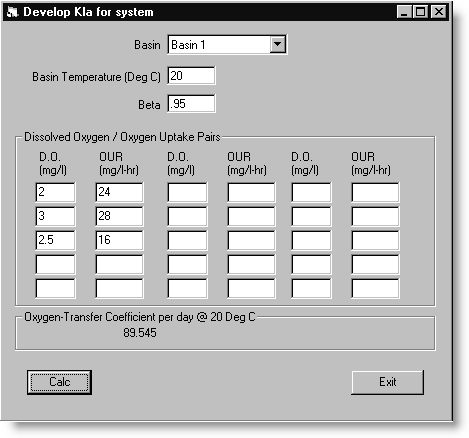
Calculates the site specific Kla (Oxygen Transfer Coefficient) based on provided DO and Oxygen Uptake Rates. The calculated Kla is used in other parts of modeling to predict oxygen requirements. |
 |
Modeling the aeration system of an Activated Sludge process starts with of determining the ability of the site specific aeration devices to supply oxygen. The textbook equation uses the term, KLa as the Oxygen transfer coefficient and is calculated by inputting sets of dissolved oxygen (D.O.) & oxygen uptake rates (OUR). This coefficient is a function of aerator power input, aerator configuration, basin geometry, temperature, and other liquid properties. Oxygen transfer rates quoted by equipment vendors are for specific conditions, usually clean (tap) water with a single aerator in a test basin. These conditions are far different from those existing in an actual aeration basin. The most accurate way to predict oxygen transfer capacity, then, is to use an in-place determination of Kla (see notes for equation used.) The following screen will appear:

USING:
Good data collection methods are essential to the success of this routine. Enough pairs of dissolved oxygen (D.O.) & oxygen uptake rates (OUR) must be taken to be truly representative of the oxygen transfer capability. These measurements should be made on a grid throughout the aeration basin to consider both plan and vertical variations caused by non-idealities in mixing. These tests should be made when there are reasonably steady state conditions and with a fixed number of aerators and/or blowers operating. It would make the most sense to run this analysis with the maximum normal condition (example: Three blowers running, one on standby. Then with two blowers running, the oxygen capacity would be 66% of that shown).
FIELDS:
Basin Use the Pull-Down List to select the basin.
Basin Temperature (Deg C) Enter the temperature of the Mixed Liquor for which the data pairs were taken.
Beta: Enter the value of Beta. For municipal wastewater, 0.95 to 1.0 is typically used (EPA 1989) and a generally accepted default is 0.95. Technically it is the ratio of saturation concentration of oxygen in wastewater to local tap water.
B = DO Saturation Concentration of Wastewater / DO Saturation of local tap water
D.O.: Enter the value of Dissolved Oxygen associated with its pair...
OUR: Enter the value of Oxygen Uptake Rate associated with a D.O.
Note: A KLa for each basin is required in order to see overall oxygen transfer capacity.
BUTTONS:
 |
Calculates the Oxygen Transfer Coefficient (KLa) for the data pairs entered. A dialog box will ask whether to save the value. Answer Yes, to save the value to proceed to the next routine, Generate Oxygen-Transfer Capacity Curve. A saved KLa for each basin should be calculated before proceeding in Oxygen Analysis.
|
 |
Exits the Modeling section. Unless the Calc button was used, the new KLa will not be saved. |
NOTES:
Equation for Kla:
Kla V (BCs - C) = (rX)V
Where: Kla = oxygen mass transfer coefficient (1/day)
V = Volume of aeration basin (l)
B = Beta (ratio of saturation concentration of oxygen in wastewater to local tap water)
Cs = saturation concentration of oxygen in pure water (mg/L)
C = oxygen concentration in MLSS (mg/L)
rX = microbial oxygen uptake rate (mg/L-day