UDG1000 can read data from an sc200 via Modbus RTU/ASCII. In order for UDG1000 to read data from the sc200 it must be connected to the USB port via a U-Links or to the Serial Port via an Adam:
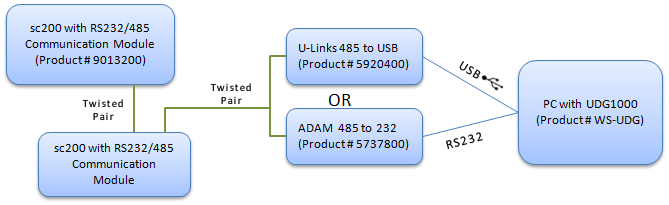
In this example, we will connect a single sc200 to UDG1000 via a U-Links adapter.
1. Install the ULinx USB Drivers (Note: The drivers for the ULINX USB to Serial converters will support Windows 2000, XP, Vista, and Windows 7 (32 and 64 bit).) .
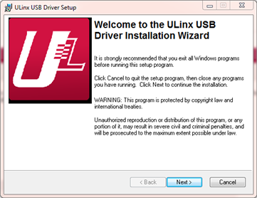
Click Next:
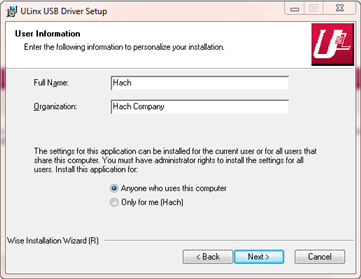
Fill in your name, organization and select the "Anyone who uses this computer" option. Click Next:
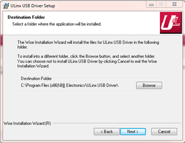
Take the default Destination folder and click Next.
Click Next and the drivers will be installed.
Click Finish.
2. Connect the ULinx to your sc200 Modbus Comm Module:
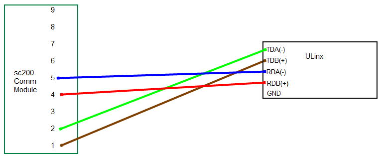
On the back of the ULinx, the settings are as follows:
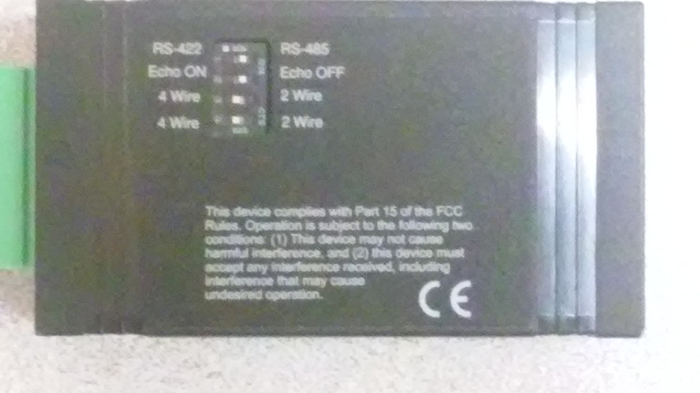
- RS-485 (to the right)
- Echo OFF (to the right)
- 4 Wire (to the left)
- 4 Wire (to the left)
The twisted pair wire must connect the Ext Network Connection to the ADAMtm-4520 converter. Open the sc100 and looking at the inside door you will see the Ext. Network Connection:
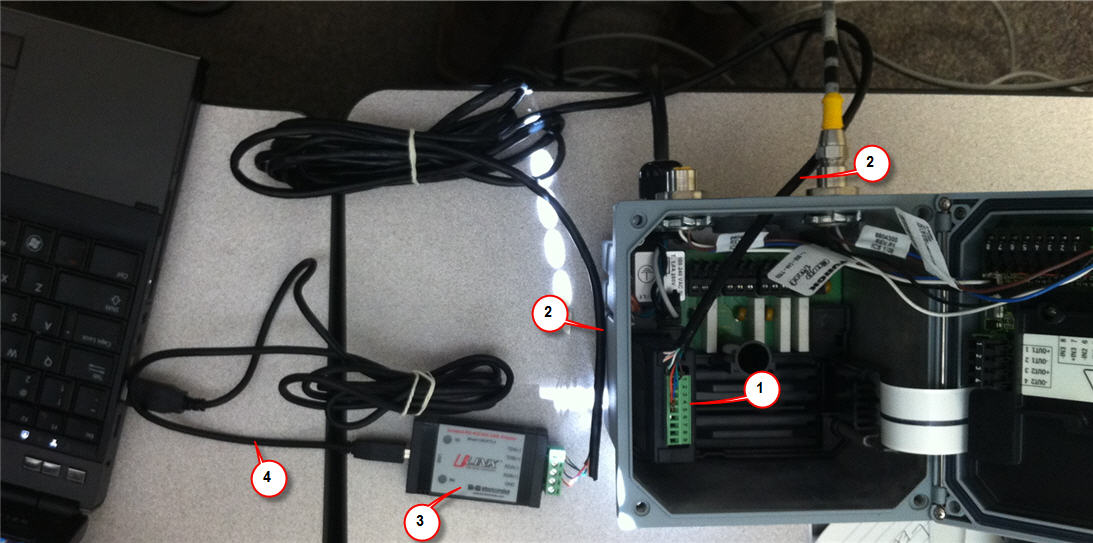
| 1 |
sc200 Comm Module |
| 2 |
4 wire connection from Comm Module to ULinx |
| 3 |
ULinx RS485 to USB converter |
| 4 |
USB cable connection from ULinx to PC USB Port |
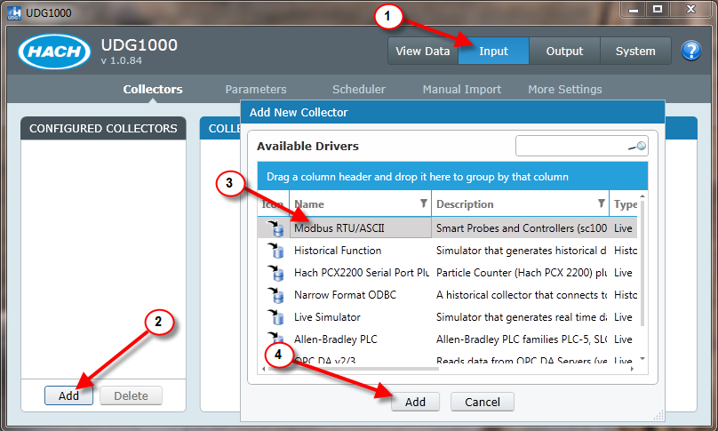
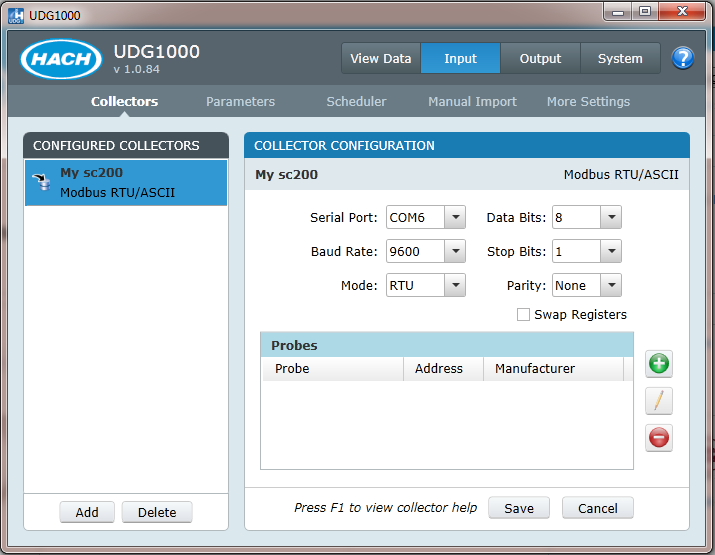
3. Add the Modbus RTU collector
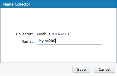
2. Name the instance of the collector
3. Setup the Communication Parameters to match the sc200.
On the sc200, go to Menu>Network Setup and verify that the Modbus Mode,Baud Rate, Parity, and Stop Bits match the UDG1000 settings. Note, on the sc200 the Data Bits is always 8. The UDG1000 Swap Registers setting corresponds to the Data Order on the sc200. DO NOT CHECK the UDG1000 Swap Register setting if sc200 is set to “Little Endian” (default). Check setting if sc200 is set to “Big Endian”:
4. Add the Probe to UDG1000:
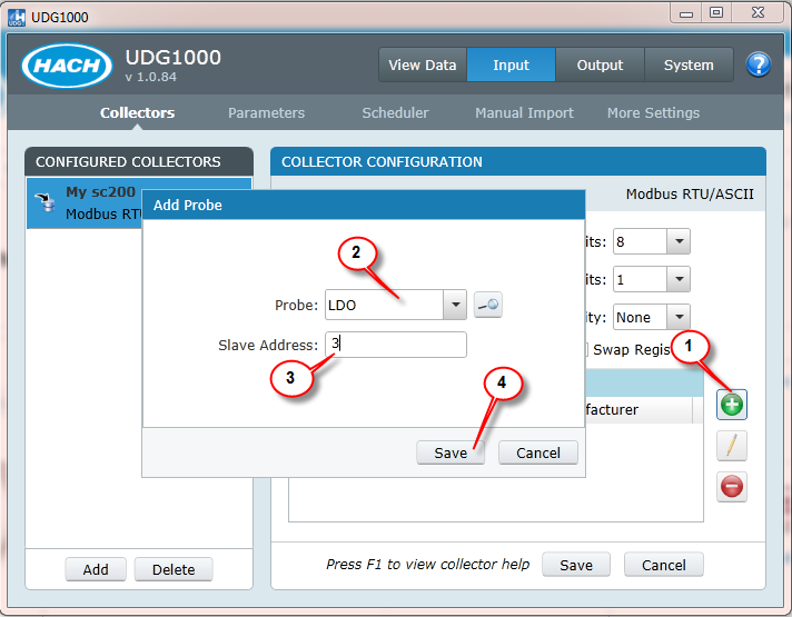
| 1 |
Click the + button to add a Probe |
| 2 |
Choose your Probe from the drop down list - In this example, you have an LDO probe. |
| 3 |
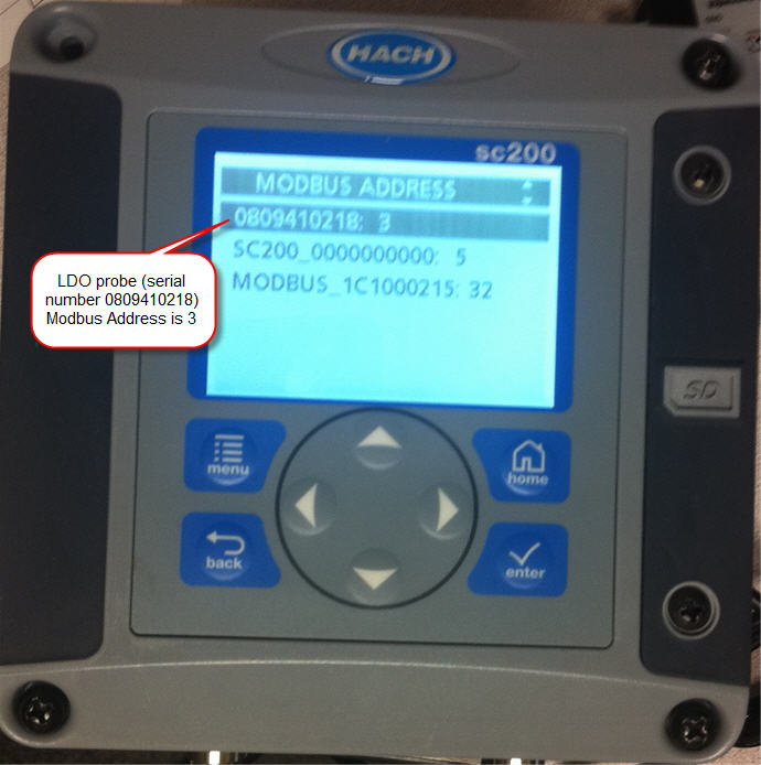
Enter the Slave Address. To find this address on the sc200, go to Menu>Network Setup>Modbus Address. The sc200 will display the address of all it's probes and it's own Modbus address.
|
| 4 |
Click Save |
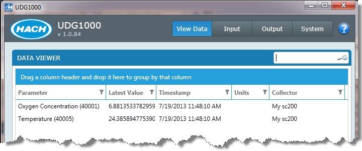
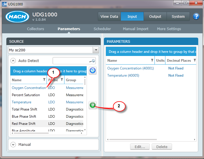
5. Choose Parameters to be tracked:
6. View the data: